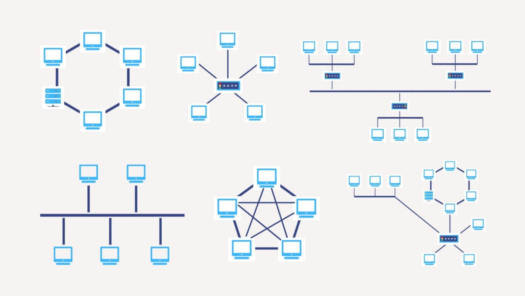
Network Topology Diagrams show the relationship of hardware, software and communications in a computer network. They describe the physical connections between devices, as well as their logical interconnections.
Network Topology Diagrams
Network topology diagrams are a visual representation of the physical layout of a network. They show how the computers and other devices in an organization are connected to each other, and can be used to help determine where problems might be occurring.
In this diagram, the network topology is shown as a cloud. This means that it is distributed. The nodes are connected to each other via a series of links. Each node can be seen as a separate computer system or server, while the links represent the physical connections between them.
This network topology diagram shows a three-tier architecture with clients, servers, and the internet. The clients are connected to the servers through a local area network (LAN). The servers are connected to the internet through a wide area network (WAN).
 |
| Monitoring Tool In Networking |
This diagram shows a simple example of a network topology. The network consists of two computers, A and B, connected by a router. The computers can be any type of device that connects to the internet and is capable of running an operating system. The router is a device that provides the connection between two networks (the computers).
Network Topology is a graphical representation of the physical layout of a computer network. It shows how data travels around the network and how nodes are connected.
The diagram above shows a typical network topology.
-Hosts are connected to each other via switches.
-The networks are connected to the hosts via network adapters
